Magnetic Gradients Tomography Technology for Non-Contact Inspection of Unpiggable Pipelines
Introduction
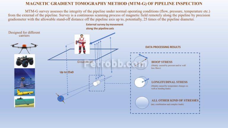
The Magnetic Gradients Tomography Method (MTM-G) is a brand new extremely efficient technology for non-contact inspection of pipelines.
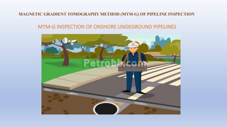
The MTM-G Method was created during the development of the Magnetic Tomography Method (MTM), itself developed nearly 20 years ago. However, the Magnetic Gradients Tomography Method provides more precise information on pipeline integrity, in comparison to the MTM Method and allows for the inspection of underground pipelines at a depth equivalent to 25 times the pipeline diameter from the inspection tool.
From a Physics point of view, MTM-G is based on the fundamental discovery of inverse magnetostriction “Villari Effect”, linking mechanical stresses and magnetic properties of ferromagnetic objects. The principle is based on mechanical stresses recorded by the measured characteristic of the magnetic field of the extended ferromagnetic structure.
What is the Villari Effect?
The Villari Effect is a change in Magnetization due to Applied Stress
MTM-G is:
Based on the inverse magneto strictive effect, the Villari Effect, which is the change of magnetic susceptibility of a ferrous material when subjected to a mechanical stress.
MTM-G uses the NATURAL magnetization of the ferrous pipe by magnetic field of the earth, where MTM-G equipment remotely registers magnetic fields from the pipe while moving along its axis.
It does not measure the dimensions of geometric defects. Instead, it measures the stress caused by these defects and identifies their type, location and the orientation of the area of stress.
MTM-G determines the comparative degree of danger of defects by a direct quantitative assessment of the stress-deformed state of the metal.
In MTM-G, if a downward or upward force is applied to the upper or lower part of the pipe, its magnetic response will be immediately detected by a magnetometer. This phenomenon is called: THE MAGNETIZATION OF THE STRESS STATE OF A FERROMAGNETIC MATERIAL.
Ranking of pipeline sections with defects using categories of technical conditions allows the justification of their repair or reconstruction by replacement.
The conventional ILI system for technical diagnostics has a number of drawbacks.
Some of these are:
- The primary detection of suspected cracks located in an unknown direction is difficult (they can occur in longitudinal, transverse direction, and at an angle to the axis of the object, but the sensors are not omni-directional).
- To date, there is no generally accepted algorithm for assessing crack resistance and predicting the rate of development of crack -like defects based on the life-cycle mechanism in the form of a “bath”.
- There are no uniform quantitative criteria for assessing the risk of the ILI of pipeline defects of various types that would take into account the specific operating conditions of the pipelines.
- Conventional ILI does not provide methods for assessing the degree of degradation of metal properties in aggressive embrittlement (hydrogen) conditions such as microbial induced corrosion (MIC) or SCC and SSC.
- The latter is applied to conditions of increased static or cycling loads with stress-deformed state anomalies. There are pipeline sections with free spanning, corrugation, stress-strain-torsion levels above acceptable limits, with loss of stability, for example, due to washout (removal) of soil during heavy rains, in landslide areas, mountainous terrain, seismically active zones, permafrost and mountain soils, mine works, as well as underwater (offshore) pipelines.
- The main problem with the conventional ILI method is that the degree of stress concentration in a particular section of the pipeline is not taken into account and local stress concentrators are not considered.
- Stress is assessed and estimated by the engineers of the operating organization.
- Very often it is not possible to discriminate metal loss defects from imperfections of pipe material (non-dangerous non-metallic inclusions into pipe material) on ILI records and this can influence conclusions made on pipeline integrity.
- Prior to obtaining reliable results from ILI tools, the inner pipeline cavity must be sufficiently cleaned through multiple runs with cleaning pigs.
- In-Line Inspection requires the availability of launching & receiving traps for ILI tools in each pipeline section, which is costly, especially for big diameter pipelines (the price of one trap can reach 150,000 Euros per installation).
- For ultrasonic In-Line Inspection, perfect inner cleaning and availability of liquid flow in the pipeline is required.
- For ILI in gas pipelines, the gas flow rate must not exceed 2.5 m/second for good results. Such a reduction in the gas flow rate is economically not profitable for pipeline operators.
Advantages of MTM and MTM-G Over Conventional Diagnostic Methods for Unpiggable Pipelines
- Does not require special preparation of the pipeline or reduction of product flow rate in the pipeline
- Allows for diagnosing in areas inaccessible for in -pipe and contact methods of flaw detection
- Guarantees high detection accuracy in areas with crack-like defects and stress-deformed anomalies (75-80% for MTM and 90-95% POD for MTM-G). Pipeline operation possesses additional risks if there are stress-corrosion cracking defects in unpiggable pipelines, where the use of ILI is impossible or inappropriate. MTM technology, patented in the USA and Canada using the magnetic tomography method regulated by the Russian guidance document RD102–008–2002, is aimed at solving this problem. The MTM-G technology solves this problem using much higher resolution than MTM.
- Is high performance (up to 7 km per day for a single team of 3 specialists, walking the pipeline route with portable equipment)
- Detects a wide range of defects in the main and welded metal and has high accuracy in assessing the degree of danger, taking into account existing loads
- Easy to organize automatic monitoring of the development of crack-like defects in areas of any length and width in any time interval
- Low cost of services compared to programs requiring pipe digging, surveys and contact methods using NDT tools
- The resolution of MTM & MTM-G tools is much higher than contact NDT tools
As an example of the detection of SCC defects for inspected pipelines in Russia (Siberia Region), India, Malaysia, as well as other countries, the total probability of detecting (POD) anomalies in areas with SCC defect zones with longitudinal cracks reaches 85% for MTM and 95% for MTM-G.
In addition to longitudinal cracks, MTM and MTM-G successfully detect both circumferential and angle defects, (for example micro cracks in welded mounting connections and spiral welded pipes)
- The undoubted advantage of MTM & MTM-G methods is the ability to monitor, in real time, the development of SCC defects by installing special contactless sensors.
- The sensors monitor the growth of local mechanical stresses in the vicinity of the defects selected from the MTM and MTM-G results that show maximum stress concentration.
- The essence of the MTM & MTM-G lies in the interrelation of the parameters of the magnetic field of a pipeline with mechanical stress levels in the metal of the pipe. The method allows for the detection of local concentrations of mechanical stress caused by metal defects. This is a fundamental advantage over other technologies and especially relevant for offshore pipelines
One of the headaches on offshore pipelines is free spanning. In a pipeline free span zone, the stress in the pipe metal increases significantly. Therefore, even a minor defect can be critical, since the overall stress level in the pipe can be in just a step away from the breakdown stress.
The problem of free spans and undersigned bends of pipelines is vital in Iranian mountainous areas with seismic activities, where a great number of pipelines are laid. MTM & MTM-G methods efficiently detect all stress zones in these areas, assisting pipeline operators to repair pipelines in a timely manner, thus maintaining pipeline integrity and ensuring proper operation.
In the case of free spanning, even on pipelines equipped for In-Line Inspection, it is not always possible to correctly assess the degree of danger for a defect as it is impossible to take into account all the existing forces acting on the pipeline. It is here that the MTM and MTM-G methods provide a direct answer: YES! The MTM and MTM-G methods are capable of estimating the stresses that occur in a pipeline during operation in actual conditions.
The stress in pipe metal, calculated as a result of the MTM and MTM-G results arising from defects, external impacts and/or a stress-deformed states, reflects the actual technical condition of the pipeline. The accuracy of this stress calculation was confirmed by “PETRONAS” during a mock up test.
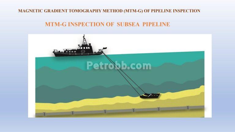
Additional Advantages of MTM and MTM-G Methods Especially Beneficial for Offshore Pipelines:
- There is no need to connect special equipment to the pipeline. The maximum distance from the axis of the pipeline to magnetometer moving above the pipe should not exceed 15 times the diameter of the pipeline being examined using MTM and 25 times the diameters using MTM-G.
- Aqua MTM and Underwater KORD-SV (MTM-G) subsea inspection equipment using ROVs, can be carried out in the free fly mode. It is important to maintain the position of the ROV above the pipeline axis and to maintain a vertical distance.
- As a result of an inspection, the pipeline operator receives a report reflecting the actual technical condition of the tested pipeline based on actual stresses in the pipe metal.
- In the report a pipeline operator receives, among other information, data on the effective stresses in each identified anomaly, as well as the period of incident-free operation, that is, T(safe), P(safe) and ERF.
- Based on the inspection data and at the request of the customer, a risk map indicating the most dangerous sections, forecasting the development of conditions over time as predictive and proactive functions can be created for the inspected pipeline.
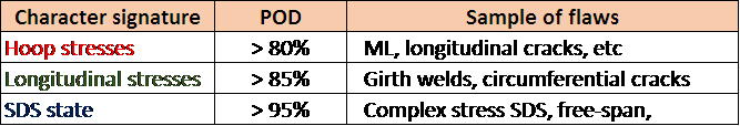
POI figures are as follows:
- POI for corrosion defects: 80% for MTM and 85% for MTM-G
- POI for dents: 80-90% for MTM and 95% for MTM-G
- POI for crack-like anomalies (under load): 75% for MTM and 90% for MTM-G.
And finally:
The main difference between the non-contact Method of Magnetic Gradients Tomography (MTM-G) with other existing magnetic measurement methods is the possibility of detecting existing magnetic anomalies in inspected pipelines as well as the degree of severity, and the possibility to transform the fields of magnetic gradients into fields of mechanical stress gradients, using data calibration. As a result, the fields of mechanical stress are classified by their types and shapes for more precise assessment of pipeline integrity with recommendations for further safe operation of the inspected pipeline.
More detailed MTM-G information makes it possible for pipeline operators to concentrate on the types of stresses that meet safety requirements for the exact pipeline and/or the exact requirements of the project.
For example, bend stresses in bend joint zones will not significantly restrict maximum allowable operation pressures as the appearance of metal loss defects in a pipeline bend zone. Therefore, information on hoop stresses around such defects will allow for the determination of criteria for maximum safe operation pressures more accurately.
MTM-G inspection tools contain more high resolution sensors than MTM tools, aimed at the recording of magnetic field gradients. MTM-G also has a special configuration of the sensors oriented in three planes, specially designed for the separate assessment of hoop, longitudinal and other mechanical stresses independently from each other.
It is possible to adjust MTM-G technology to focus on each specific project (or even on pipeline) integrity task. T-safe (and RLA) can be assessed based on the actual pressure at the time of the survey. This can also be assessed for anticipated pipeline operation pressures.
| No. | Parameter | Value |
| 1 | 100% of the pipeline length can be inspected using MTM-G technology | |
| 2 | 100% accuracy can be reached for the inspection of horizontal pipelines if the survey complies with MTM-G specifications | |
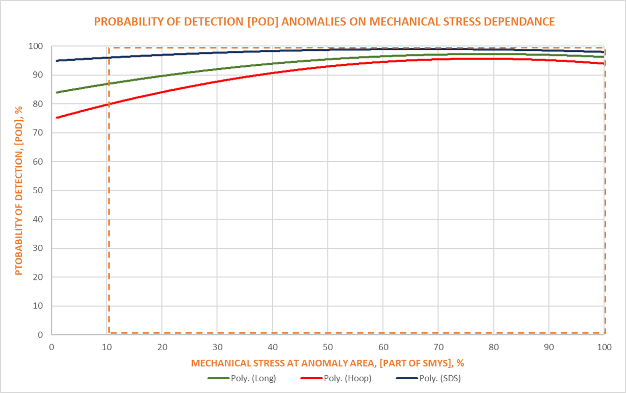
| 3 | POD of anomalies caused by SDS | >95% |
| 4 | POD of anomalies associated with all types of anomalies | >80% |
| 5 | Hoop stress >40% SMYS | >85% |
| 6 | Longitudinal stress >30% SMYS | >85% |
| 7 | Probability of Identification (POI) by degree of danger (ref. to stress) | >85% |
| 8 | Probability of Classification (POC) by stress signature | >80% |